📚T-JSON Protocol


©️Copyright
This agreement is the exclusive property of Tofu Intelligence® and is protected by copyright laws and treaties. It may not be reproduced or copied for other uses without authorization.
The agreement provides a test client for docking and the source code to facilitate quick application for customers.
1. Must-Read
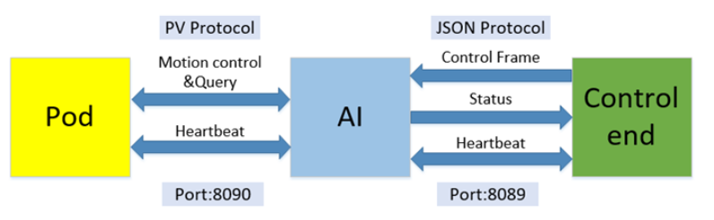
This agreement specifies the communication methods and protocols between the AI end and the control end, as well as between the AI end and the pod.
⚠Note that the pod referred to in this agreement specifically means the Tofu model pod. Other pods and gimbals are not applicable to the PV protocol communication method.
This agreement is applicable to any operating system and can be used for secondary development of client software.
(Ignore this part if you are not a pod user 🔽)
During operation, the AI end directly controls the gimbal and lens. The AI end acts as the server (Server end), while the pod and lens control end act as the client (Client end). The AI port number is 8090. The PelcoD protocol and VISCA protocol are used, hereinafter referred to as the PV protocol. The control and query cycle is set to 200ms by default. If you are using a gimbal camera, this part can be ignored, and only the JSON protocol is needed. All network communication is based on the TCP/IP method.
(Ignore this part if you are not a pod user 🔼)
The control end supports switching of AI end algorithm modes and parameter configuration; reception of information during recognition and tracking processes; and manual control of the gimbal and lens. The AI end acts as the server (Server end), while the control end acts as the client (Client end). The AI port number is 8089. The JSON protocol is used. The interval between all JSON data frames must not be less than 300 milliseconds.
The AI end uses the RTSP protocol to transmit video, with H.264 encoding as the default (which can be modified to H.265 through the T-JSON protocol). The port number is 554. When the AI camera node is powered on, the RTSP Server is started to wait for video on-demand. The control terminal needs to view the video by subscribing to the video through the RTSP URL. The T-JSON protocol does not include the video stream part. Please use the RTSP video parsing method on your own for video stream parsing. No related code or technical support for this part is provided at the moment.
In the network link, all devices connected to the AI end must follow the heartbeat frame rule.
2. PV Communication Protocol
(Ignore this section if you are not a pod user)
The AI end communicates with the pod using the PV protocol. Among them, the gimbal movement and query-related commands use the PelcoD protocol, while the lens zoom, focus, and query-related commands use the VISCA protocol.
The communication does not include data other than the commands, and it can be directly sent and received through the network port. Here are a few commonly used protocol commands.
For the complete protocol, please refer to the PelcoD Gimbal Control and VISCA Lens Control Protocol document. If you are using a gimbal camera, you can ignore this section and simply use the JSON protocol.
3. T-JSON Communication Protocol
The T-JSON communication protocol is used for communication between the client and the AI end. It enables control and configuration of the AI end, retrieval of AI end status messages, manual control of the gimbal and lens, and acquisition of target screenshots.
The T-JSON protocol consists of the JSON Command Protocol and the Image Capture Protocol, both communicating through the same port 8089.
In the following frame descriptions, "Tofu Product" represents the server side, and "Client Software/Platform Software" represents the client side.
🟢 JSON Command Protocol Format:
| Identifier 1 | Identifier 2 | Frame Type | Frame Length | Frame Content |
|---|---|---|---|---|
| 1 Byte | 1 Byte | 1 Byte | 4 Bytes | N Bytes |
| 0xEC | 0x91 | See Frame Type Table | Length N of content |
JSON |
Frame Type Table:
| Frame Type | Type Name | Format |
|---|---|---|
| 0x01 (Device → Client) | Status Frame | JSON |
| 0x03 (Client → Device) | Control Command | JSON |
| 0x04 (Device → Client) | Image Capture (See Image Capture Protocol) | JPEG Socket |
| 0x05 (Client → Device) | Image Info Query | JSON |
| 0x06 (Client → Device) | Set Target Detection Area | JSON |
| 0x07 (Client → Device) | Set Display Mode | JSON |
| 0x08 (Client → Device) | Set Algorithm Model | JSON |
| 0x09 (Client → Device) | Set Target Capture Status | JSON |
| 0x11 (Bidirectional) | Heartbeat | Socket |
| 0x12 (Bidirectional) | ACK | Socket |
🟢 Image Capture Protocol Format:
When the image capture (target screenshot) function is enabled, screenshots of detected target areas are sent in real-time via Socket through the same port (8089) as the JSON protocol. Each target is packaged individually. For example, if there are 3 targets in an image, the protocol sends three separate Socket packets.
| Identifier 1 | Identifier 2 | Frame Type | Frame Length | Location Info | Frame Content | Frame Check | End Tag 1 | End Tag 2 |
|---|---|---|---|---|---|---|---|---|
| 1 Byte | 1 Byte | 1 Byte | 4 Bytes | 8 Bytes | N Bytes | 1 Byte | 1 Byte | 1 Byte |
| 0xEB | 0x92 | 0x04 | JPEG Size (N) |
Location | JPEG Data | Checksum | 0xFB | 0x92 |
Location Info:
Coordinates of the captured image within the original image, including in order:
- Left X-coordinate (2 Bytes)
- Top Y-coordinate (2 Bytes)
- Width of the captured image (2 Bytes)
- Height of the captured image (2 Bytes)
(Coordinate origin (X=1, Y=1) is at the top-left corner of the image)
Frame Length:
Byte count of the JPEG image data, corresponding to N in the table above.
Frame Check (Checksum):
Checksum of the 7 Bytes: 0xEB + 0x92 + 0x04 + Frame Length (4 Bytes).
4. JSON Frame Content Description
4.1 Server to Client Frame Content
4.1.1 Algorithm Information
Algorithm Information Data Structure Description:
| Key | Disp. | Value | Type |
|---|---|---|---|
| ControlType | Control Type | AIInfo | String |
| WorkMode | Work Mode | 0x01: Recognition 0x02: Auto Tracking 0x03: Click Tracking 0x04: 🪄Wave gate/Box Tracking |
Int |
| ObjectCount | Total Targets | N | Int |
| Object | Target Information | See below | JSON |
🪄
Wave gate tracking is a tracking method with a fixed-size selection box.
Object Format Description:
| Key | Disp. | Value | Type |
|---|---|---|---|
| Class | Target Type | 0xA1: Person, 0xA2: Vehicle, 0xA3: Boat, 0xA4: Drone, 0xB1: Tracking Normal, 0xB2: Tracking Lost |
Int |
| Point | 🪄Position Information | Left: Left X, Top: Top Y, Right: Right X, Bottom: Bottom Y |
Int |
| Distance | Distance Information | N | Double |
🪄
Point: The position of the target box, with the top-left corner as the origin (0,0).
Range:
Visual camera: Left, Right 0-1919; Top, Bottom 0-1079.
Thermal camera: Left, Right 0-719; Top, Bottom 0-575.
During tracking, only the coordinates of the tracked target are pushed. When tracking is lost, the coordinates are 0, 0, 0, 0.
⚠Not all devices have Distance information. If available, the unit is m (meters).
JSON Example:
{
  "ControlType": "AIInfo", // Control type, indicating this is an AI algorithm information push
  "WorkMode": 1,           // Work mode, 0x01 indicates recognition mode
  "ObjectCount": 2,        // Total targets, indicating the number of detected targets

  "Object": {              // Target information collection, each target identified by a unique ID
    "01": {                // Target ID "01"
      "Class": 161,        // Target type, 0xA1 indicates a person
      "Points": {          // Target position information in the image (bounding box)
        "Left": 100,       // Top-left X coordinate of the bounding box
        "Top": 100,        // Top-left Y coordinate of the bounding box
        "Right": 200,      // Bottom-right X coordinate of the bounding box
        "Bottom": 200      // Bottom-right Y coordinate of the bounding box
      },
      "Distance": 1066.0   // Target distance (unit: meters)
    },
    "02": {                // Target ID "02"
      "Class": 162,        // Target type, 0xA2 indicates a vehicle
      "Points": {          // Target position information in the image (bounding box)
        "Left": 300,       // Top-left X coordinate of the bounding box
        "Top": 100,        // Top-left Y coordinate of the bounding box
        "Right": 400,      // Bottom-right X coordinate of the bounding box
        "Bottom": 200      // Bottom-right Y coordinate of the bounding box
      },
      "Distance": 1182.0   // Target distance (unit: meters)
    }
  }
}
JSON Example During Tracking:
{
  "ControlType": "AIInfo", // Control type, indicating this is an AI algorithm information push
  "WorkMode": 2,           // Work mode, 0x02 indicates auto-tracking mode
  "ObjectCount": 1,        // Total targets, indicating the number of detected targets is 1
  "Object": {              // Target information collection, containing detailed information of each detected target
    "01": {                // Target ID "01", representing the first target
      "Class": 177,        // Target type, 0xB1 indicates tracking normal (specific classification depends on actual definition)
      "Points": {          // Target position information in the image (bounding box)
        "Left": 220,       // Top-left X coordinate of the bounding box
        "Top": 450,        // Top-left Y coordinate of the bounding box
        "Right": 250,      // Bottom-right X coordinate of the bounding box
        "Bottom": 490      // Bottom-right Y coordinate of the bounding box
      },
      "Distance": 1055.0   // Target distance (unit: meters), indicating the distance of the target from the camera
    }
  }
}
4.1.2 Device Status Information
Device Status Information Data Structure Description:
| Key | Name | Value | Type | Disp. |
|---|---|---|---|---|
| ControlType | Control Type | ZoomInfo | String | |
| ZoomInfo | Lens Zoom Rate | Accurate to one decimal place | Double | |
| PTZInfoH | Gimbal Horizontal Angle | Accurate to one decimal place | Double | |
| PTZInfoV | Gimbal Vertical Angle | Accurate to one decimal place | Double | |
| LaserRange | Range Measurement | Accurate to one decimal place | Double | Supported by some devices |
| CamShowMode | Camera Display Mode | 0: Color; 1: Mono | Int | Supported by some devices |
| Latitude | Latitude | Accurate to six decimal places | String | Supported by some devices |
| Longitude | Longitude | Accurate to six decimal places | String | Supported by some devices |
| Height | Height Measurement | Accurate to one decimal place | Double | Supported by some devices |
JSON Example:
{
  "ControlType": "ZoomInfo", // Control type, indicating this is a device status information push
  "ZoomInfo": 3.6,           // Lens zoom rate
  "PTZInfoH": -50.3,         // Gimbal horizontal angle
  "PTZInfoV": 16.4,          // Gimbal vertical angle
  "LaserRange": 810.0,       // Range measurement, indicating the result of laser ranging, unit is meters
  "CamShowMode": 0,          // Camera display mode, 0 indicates color mode
  "Latitude": "39.836502N",  // Latitude information, N indicates north latitude
  "Longitude": "116.287451E",// Longitude information, E indicates east longitude
  "Height": 888.0            // Height information
}
4.2 Client to Server Frame Content

Includes work mode configuration and data transmission.
4.2.1 Work Mode
Work Mode Configuration Command Format:
| Key | Disp. | Value | Type |
|---|---|---|---|
| ControlType | Control Type | SetWorkMode | String |
| SetWorkMode | Work Mode | 0x00: Turn off AI 0x01: Recognition 0x02: Auto Tracking 0x03: Click Tracking 0x04: Gate/Box Tracking 0x05: 🪄Auto Zoom On 0x06: Auto Zoom Off |
Int |
| P2Track | Configuration | See table below | Int |
🪄
Auto zoom mode refers to the function of automatically adjusting the zoom level based on the size of the target during tracking.
P2Track Configuration is required for Click Tracking and Gate/Box Tracking. The details are as follows:
| Key | Disp. | Value | Type |
|---|---|---|---|
| Center | 🪄Center Point | X: Horizontal coordinate, Y: Vertical coordinate | Int |
| Distance | Search Range/Area Size | N | Int |
| DistanceX | Search Range/Area Size | N | Int |
| DistanceY | Search Range/Area Size | N | Int |
🪄
The top-left corner of the screen is the origin (1,1); Center corresponds to the coordinates of the target center point.
In Click Tracking mode, the default Distance=30;
In Gate/Box Tracking mode, Distance (tracking box is square) or DistanceX/Y (tracking box is a rectangle of any size) can be used.
JSON Example:
{
  "ControlType": "SetWorkMode", // Control type
  "SetWorkMode": 1             // Set work mode, 0x01 indicates recognition mode
}
P2Track information is only required in Click Tracking mode and Gate Tracking mode. In Click Tracking mode, the coordinates of the click need to be provided, and the default Distance is 30. If the coordinates fall within the area of a recognized target, it will lock and track.
In Gate Tracking mode, the center coordinates and the width (height) of the tracking box are provided.
Click Tracking JSON Example:
{
  "ControlType": "SetWorkMode", // Control type
  "SetWorkMode": 3,             // Set work mode, 0x03 indicates Click Tracking mode
  "P2Track": {                  // Click Tracking configuration
    "Center": {                 // Coordinates of the target center point
      "X": 310,                 // X coordinate of the target center point
      "Y": 660                  // Y coordinate of the target center point
    },
    "Distance": 64              // Search range, indicating the search radius centered on the center point
  }
}
Box Tracking JSON Example:
{
  "ControlType": "SetWorkMode", // Control type
  "SetWorkMode": 4,             // Set work mode, 0x04 indicates Gate/Box Tracking mode
  "P2Track": {                  // Gate/Box Tracking configuration
    "Center": {                 // Coordinates of the target center point
      "X": 240,                 // X coordinate of the target center point
      "Y": 330                  // Y coordinate of the target center point
    },
    "DistanceX": 36,            // Width of the tracking area
    "DistanceY": 28             // Height of the tracking area
  }
}
4.2.2 Data Transmission
Data Transmission Command Format:
| Key | Disp. | Value | Type |
|---|---|---|---|
| ControlType | Control Type | SerialControl | String |
| SerialType | 🪄Serial Port Selection | PELCO_D VISCA |
String |
| SerialData | Data | Lens: Data Length Data: Data Content |
Int String |
🪄
For visual camera devices, if SerialType is set to PELCO_D, the data will be sent to the gimbal; if set to VISCA, the data will be sent to the camera.
🪄
When using the LIR thermal camera provided by Tofu, both SerialType=PELCO_D and SerialType=VISCA are supported.
- If **"SerialType": "PELCO_D"**, use the PELCO_D protocol to send zoom in/out and focus in/out commands to the thermal infrared module. The ID number will be automatically mapped to 0x02 and sent to the thermal infrared module through the TTL port.
- If **"SerialType": "VISCA"**, the PELCO_D protocol is also used, but note that the ID number in the PELCO_D protocol must be changed to 0x02.
For details on Pelco-D and VISCA command protocols, refer to [PELCO-D Gimbal Control and VISCA Lens Control Protocol].
The Pelco-D transmission interface can also be used to send [ExPelco-D High-Precision Gimbal Control Protocol] (requires gimbal support).
JSON Example:
{
  "ControlType": "SerialControl", // Control type, indicating this is a command for serial communication control
  "SerialType": "PELCO_D",        // Serial protocol type, specifying the use of PELCO-D protocol
  "SerialData": {                 // Serial data content
    "Lens": 7,                    // Data length, indicating the number of bytes in the subsequent data
    "Data": "FF01000800FF08"      // Actual serial data to be sent, represented as a hexadecimal string
  }
}
/*
The specific meaning of the command FF01000800FF08 is:
• Device address: 0x01
• Operation: Move up (Up), vertical speed at maximum, horizontal speed stopped.
• Checksum: 0x08
*/
JSON Example for Controlling Thermal Infrared Lens Zoom In:
{
  "ControlType": "SerialControl", // Control type, indicating this is a command for serial communication control
  "SerialType": "VISCA",          // Serial protocol type, specifying the use of VISCA protocol
  "SerialData": {
    "Lens": 7,                    // Data length, indicating the number of bytes in the subsequent data
    "Data": "FF020020000022"      // Actual serial data to be sent, represented as a hexadecimal string
    /*
    • FF: Sync byte (fixed value).
    • 02: Device address (here 0x02).
    • 00: Command category (control command).
    • 20: Specific command (zoom in operation).
    • 22: Checksum
    */
  }
}
4.3 Client Query Image Parameter Information
The query frame is sent in the following format, with a length of 7 bytes.
| Identifier | Frame Type | Frame Content |
|---|---|---|
| 0xEC 0x91 | 0x05 | 0x00 0x00 0x00 0x00 |
Query Information Feedback:
| Key | Name | Value | Type | Disp. |
|---|---|---|---|---|
| ControlType | Control Type | ImageSetting | String | |
| ImageSize | Image Resolution | 0:1080P 1:720P 2:D1 3:1440P |
int | Do not use a resolution configuration higher than the actual resolution |
| ImageBit | Image Bitrate | 512~4096 | Int | Unit is Kb/S |
| ImageCode | Encoding Format | 0:H264 1:H265 |
int |
JSON Example:
{
  "ControlType": "ImageSetting", // Control type, indicating this is a command for setting image parameters
  "ImageSize": 0,                // Image resolution setting, 0 indicates 1080P (1920x1080)
  "ImageBit": 4096,              // Image bitrate setting, 4096 indicates a bitrate of 4096 Kb/S
  "ImageCode": 0                 // Image encoding format setting, 0 indicates the use of H.264 encoding
}
4.4 Client Sets Target Detection Area
Set target detection area.
| Key | Disp. | Value | Type |
|---|---|---|---|
| ControlType | Control Type | SetValue | String |
| WarnArea | 🪄Area Setting | AreaItem:Area Marker AreaPoint:X, Y Coordinates |
Int |
🪄
When setting the area, the top-left corner of the screen is (1,1), and the maximum number of AreaPoints is 6.
JSON Example:
1. Set Detection Area:
{
  "ControlType": "SetAreaDot", // Control type, indicating this is a command for setting the target detection area
  "WarnArea": {                // Configuration of the target detection area
    "AreaItem": 1,             // Area marker, indicating this is the first detection area
    "AreaPoint": [             // Coordinates of the four vertices of the area, defining a rectangular detection area
      {
        "X": 120,              // X coordinate of the first vertex
        "Y": 100               // Y coordinate of the first vertex
      },
      {
        "X": 310,              // X coordinate of the second vertex
        "Y": 100               // Y coordinate of the second vertex
      },
      {
        "X": 310,              // X coordinate of the third vertex
        "Y": 360               // Y coordinate of the third vertex
      },
      {
        "X": 120,              // X coordinate of the fourth vertex
        "Y": 360               // Y coordinate of the fourth vertex
      }
    ]
  }
}
2. Delete Detection Area:
{
  "ControlType": "SetAreaDot", // Control type
  "WarnArea": {                // Configuration of the target detection area
    "AreaItem": 0              // Area marker, 0 indicates canceling all detection areas
  }
}
4.5 Client Sets Display Mode
| Key | Name | Value | Type | Disp. |
|---|---|---|---|---|
| ControlType | Control Type | PipShowSetting | String | |
| PipShow | Display Type | 0: Large visible light, small infrared 1: Infrared 2: Visible light 3: Fusion 16: Large infrared, small visible light |
Int | Non-dual-spectrum devices do not support this protocol |
JSON Example:
{
  "ControlType": "PipShowSetting", // Control type, indicating this is a command for setting the display mode
  "PipShow": 0                    // Display mode setting, 0 indicates "Large image displays visible light, small image displays infrared"
}
4.6 Client Sets Algorithm Model
| Key | Name | Value | Type | Disp. |
|---|---|---|---|---|
| ControlType | Control Type | ModelSetting | String | |
| Model | 🪄Algorithm Model | 0: Visible light mixed model 1: Infrared mixed model 2: Person and vehicle recognition 3: Boat recognition 4: Drone recognition 5: Aircraft and helicopter recognition 6: Bird recognition |
Int |
🪄
- Models 2, 3, and 4 are standard provided models; models 0, 1, 5, and 6 are non-standard provided models. For details, please consult.
2) Models 0 and 1 are mixed models, meaning they recognize 4 or 5 categories. When the spectral band and model do not match, it automatically switches to a compatible mixed model.
JSON Example:
{
  "ControlType": "ModelSetting", // Control type, indicating this is a command for setting the algorithm model
  "Model": 3                     // Algorithm model setting, 3 indicates the "Boat Recognition" model
}
4.7 Client Sets Target Screenshot Status
| Key | Name | Value | Type | Disp |
|---|---|---|---|---|
| ControlType | Control Type | ImageUpload | String | |
| Upload | Target Screenshot Status | 0: Target Capture Off 1: Target Capture On |
Int |
JSON Example:
{
  "ControlType": "ImageUpload", // Control type, indicating this is a command for setting the target screenshot status
  "Upload": 1                   // Target screenshot status setting, 1 indicates enabling the target screenshot function
}
5. ACK and Heartbeat Frames
5.1 ACK Frame
The server will reply with an ACK after receiving a frame from the client. If no ACK is received within 15 seconds, need to reconnect to the server.
| Identifier | Identifier | Frame Type | Frame Length | Status Code |
|---|---|---|---|---|
| 1Byte | 1Byte | 1Byte | 4Byte | 2Byte |
| 0xEC | 0x91 | 0x12 | 0x00 00 00 02 | 0x00 XX |
Status code types are as follows.
| Status Code | Description |
|---|---|
| 0x00 00 | Execution successful |
| 0x00 01 | Incomplete packet |
| 0x00 02 | Protocol content error |
5.2 Heartbeat Frame
| Identifier | Identifier | Frame Type | Frame Length |
|---|---|---|---|
| 1Byte | 1Byte | 1Byte | 4Byte |
| 0xEC | 0x91 | 0x11 | 0x00 00 00 00 |
The client must send a heartbeat frame to the server within 15 seconds. When the server receives the client's heartbeat frame, it will reply with a heartbeat within 1 second. If the client does not receive a reply within the timeout period, the client needs to resend the frame.
If the server does not receive a heartbeat frame from the client for 15 consecutive seconds, the server will determine that the client has automatically gone offline and will stop sending and receiving data.
If the client does not receive a reply from the server for 15 consecutive seconds, it should determine that the connection has been interrupted and needs to reconnect.